Tutorial 9 — Slider-crank from scratch (a real engine's crank)
Goal: build a complete slider-crank — the mechanism at the heart of every piston engine — from an empty scene, using the real dimensions of a Royal Enfield Bullet 350 (bore 70 mm × stroke 90 mm). This is your first closed kinematic loop, and it introduces the one thing the open chains of Tutorials 1–8 never did: constraint bookkeeping. Get it right and a spinning crank drives the piston back and forth over its true 90 mm stroke; get it wrong and the loop either flops loose or refuses to assemble.
Time: ~35 minutes · Prerequisites: Tutorials 2 (Revolute), 3 (Prismatic + In-Line), 5 (drive laws — we use a ramp here). Answer key: Demos ▸ Slider-Crank loads this exact model — the finished Bullet-350 slider-crank — so you can load it any time to compare coordinate-for-coordinate.
Concept — closing the loop
Everything so far has been an open chain: ground → joint → body, maybe → joint → body, always ending at a free body. A slider-crank closes the loop back to ground:
crank → conrod → slider (piston) → ground rail → back to the crank's own ground pivot.
That closure is what turns a floppy chain into a mechanism — a device where turning one input (the crankshaft) forces a definite output (the piston's stroke). It also introduces the thing open chains never hit: the joints around the loop must remove exactly the right number of degrees of freedom. Too few and the loop is loose; too many (an over-constrained loop) and the solver is told the same thing twice and can't assemble it. Counting constraints correctly is the skill this tutorial teaches — and there's one deliberate trick (Step 6) that's the whole game.
Real engine dimensions. We'll use a Royal Enfield Bullet 350 (346 cc single, bore 70 mm × stroke 90 mm). Two facts turn that spec sheet into a model:
- Crank throw = stroke ÷ 2 = 45 mm — the crankshaft's pin sits 45 mm off-centre, so one revolution sweeps the piston through 2 × 45 = 90 mm, the stroke.
- Connecting rod ≈ 150 mm — bore/stroke is the published spec; the rod length isn't, so we use a representative rod ratio L/r ≈ 3.3 (typical for a road engine — long enough that the rod barely tilts).
The geometry (everything in the XY plane, in metres; Z is the pin axis):
| Point | Where | Meaning |
|---|---|---|
| O | (0, 0, 0) | crankshaft centre — the ground pivot |
| Crank | throw 0.045 m (45 mm), node (CoM) at (0.0225, 0, 0) | O → the crank pin |
| Crank pin | (0.045, 0, 0) | crank ↔ conrod |
| Conrod | length 0.150 m (150 mm), node (CoM) at (0.120, 0, 0) | crank pin → piston |
| Slider (piston) | (0.195, 0, 0) | slides along X |
Build the three links
1. Three nodes
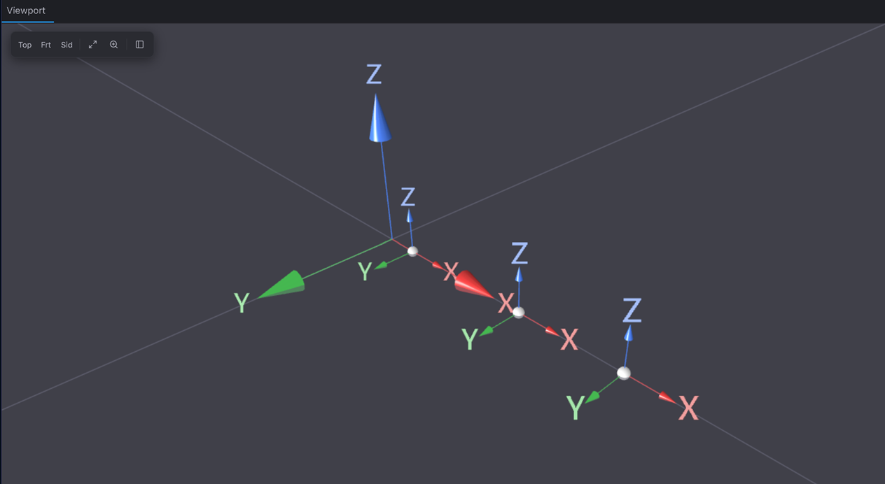
Build ▸ Node three times; open each in the Inspector and set its position: Node_Crank (0.0225, 0, 0), Node_Conrod (0.120, 0, 0), Node_Slider (0.195, 0, 0). Each node sits at the centre of mass of its link.
Expected: three node markers strung out along the +X axis, clustered near the origin (this is a small engine — a few centimetres across).
2. Three bodies
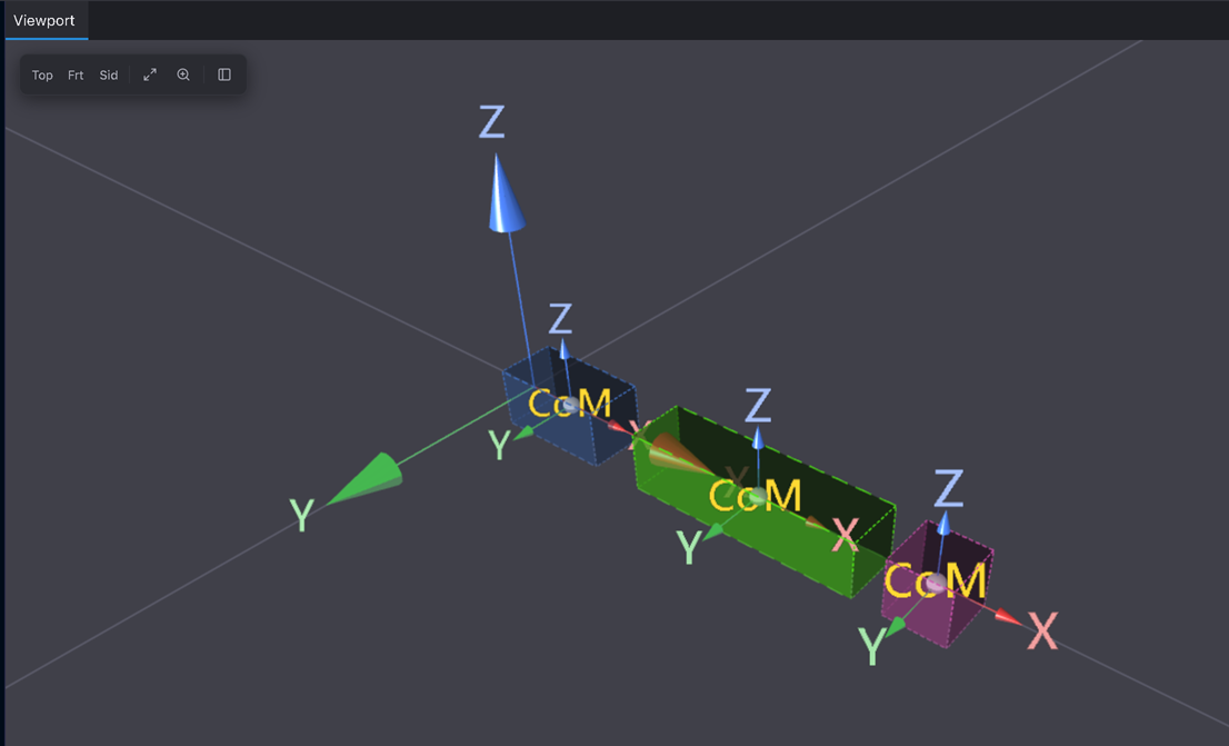
Build ▸ Rigid Body on each node (select the node first). Give each mass 1 kg and leave the inertia at its default. Name them Crank, Conrod, Slider.
Concept: the crank will be speed-driven and the loop is fully determinate, so the motion is pure geometry — masses and inertias don't change the path the piston traces, only the forces the joints carry. You can build the kinematics with defaults and revisit inertia only if you later read reactions (Tutorial 8).
Wire up the loop
3. Motorise the crank — Rotary Drive
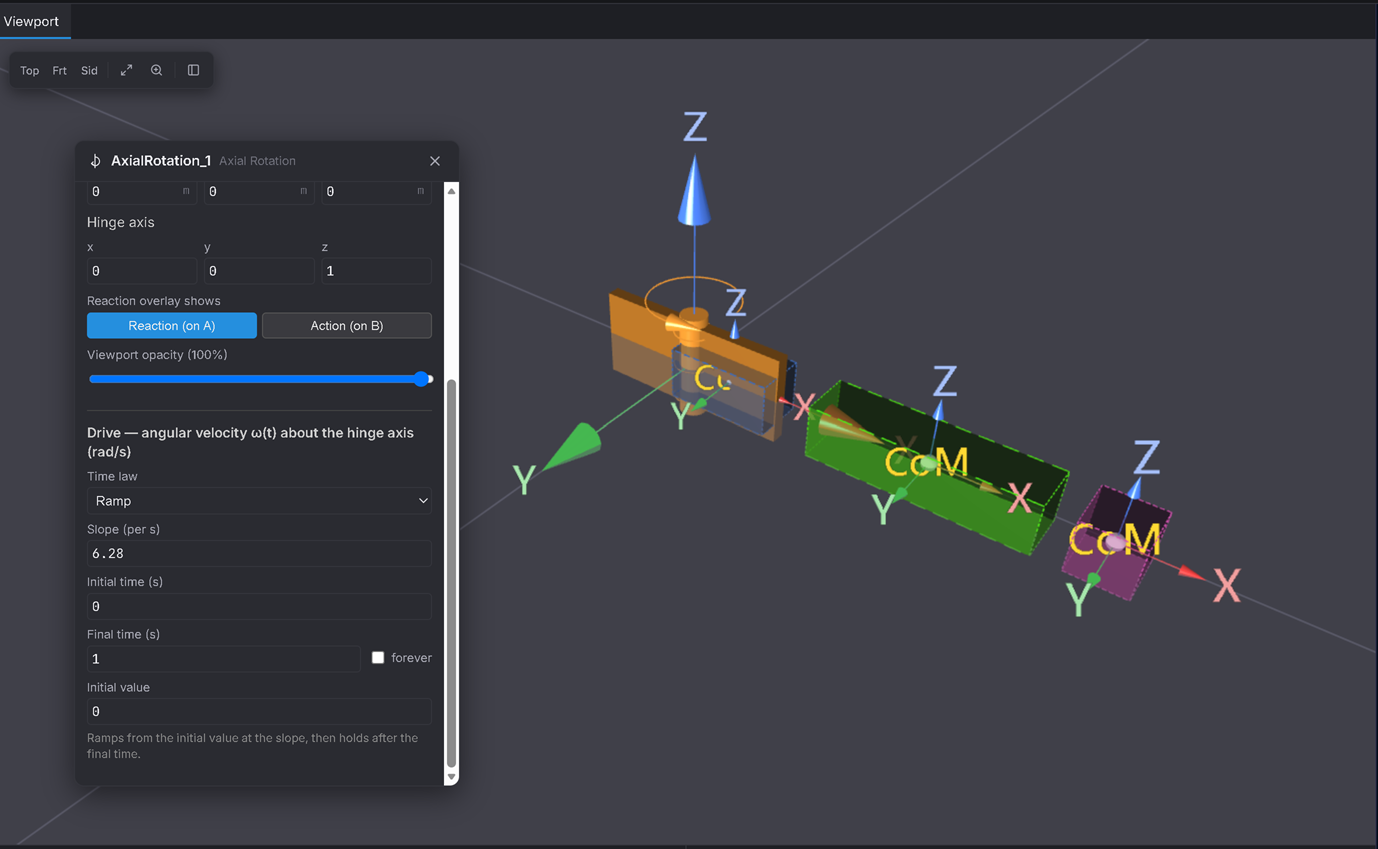
Joints ▸ Rotary Drive between Crank and Ground — the button creates an Axial Rotation joint. Set Pivot (global) (0, 0, 0) (the crankshaft centre O) and Hinge axis (0, 0, 1). In its Drive — angular velocity ω(t) section, set Time law = Ramp, Slope 6.283185 per s, Initial time 0, Final time 1 (leave forever unticked), Initial value 0 — so it spins up to 2π rad/s ≈ one revolution per second over the first second, then holds (a gentle ~60 rpm idle, easy to watch).
Expected: the crank is now motorised. Nothing else is connected yet, so on its own it would just spin about O.
4. Crank pin — Revolute
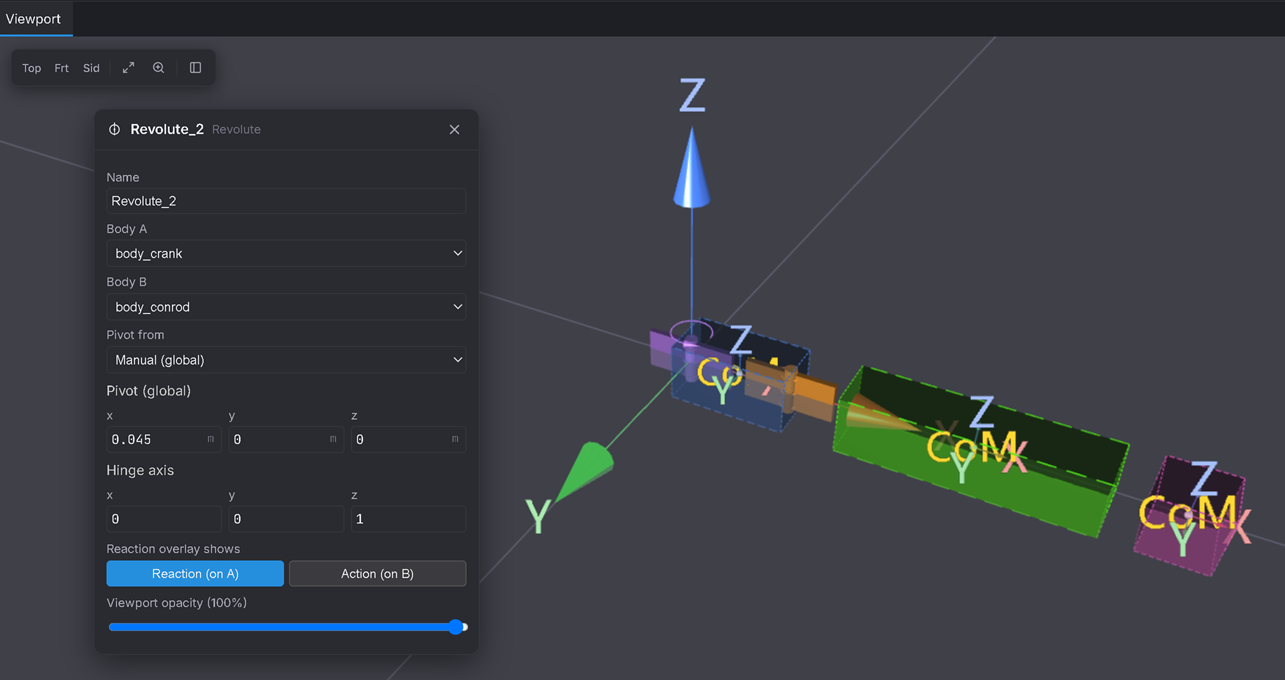
Joints ▸ Revolute between Crank and Conrod. Pivot (global) (0.045, 0, 0) (the crank pin, 45 mm off-centre), Hinge axis (0, 0, 1).
Expected: the conrod is now pinned to the crank pin and will be dragged around as the crank turns.
5. Slider on its rail — Prismatic
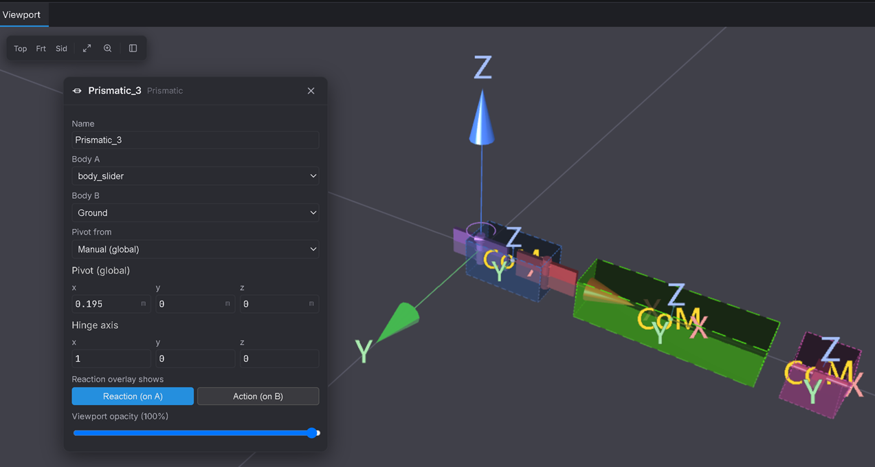
Joints ▸ Prismatic between Slider and Ground. Pivot (global) (0.195, 0, 0), and set the slide axis — the form labels it Hinge axis — to (1, 0, 0), so the piston may only travel along X (the cylinder bore's axis).
Expected: the piston is captured on a horizontal rail; it can slide along X and nothing else.
6. Conrod to slider — In-Line (the crux)
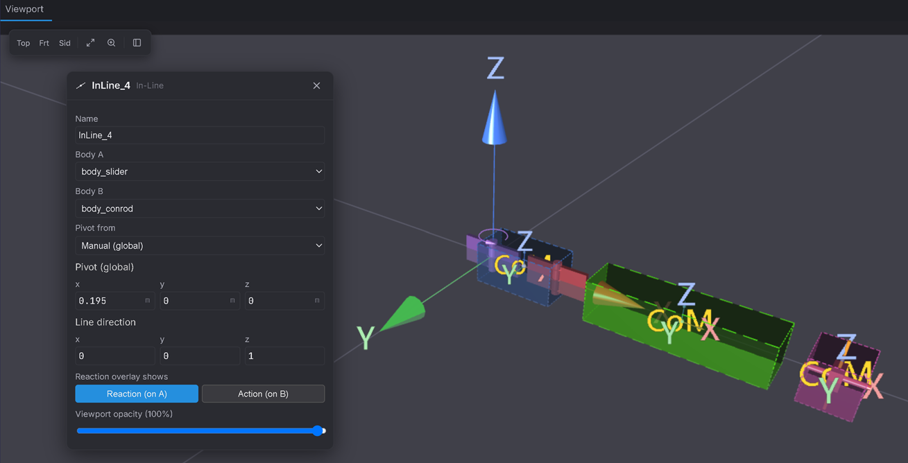
Joints ▸ In-Line between Slider and Conrod. Pivot (global) (0.195, 0, 0), Line direction (0, 0, 1) (the In-Line form calls its axis "Line direction").
Why In-Line and not another Revolute? This is a planar mechanism built inside a 3D solver. The piston is already fully located across the rail by the prismatic (Step 5); it only still needs the conrod's end tied to it within the plane. A full Revolute here would re-specify constraints the prismatic already supplies — an over-constrained, redundant loop that fights itself and often won't even assemble. The In-Line is a lighter "planar pin": it locks the two points together in the plane (removing the two in-plane translations) but leaves rotation free — so the loop comes out exactly determinate. This single choice is the difference between a mechanism that runs and one that jams.
Run it
7. Solve and watch the stroke
Solve for 3 s.
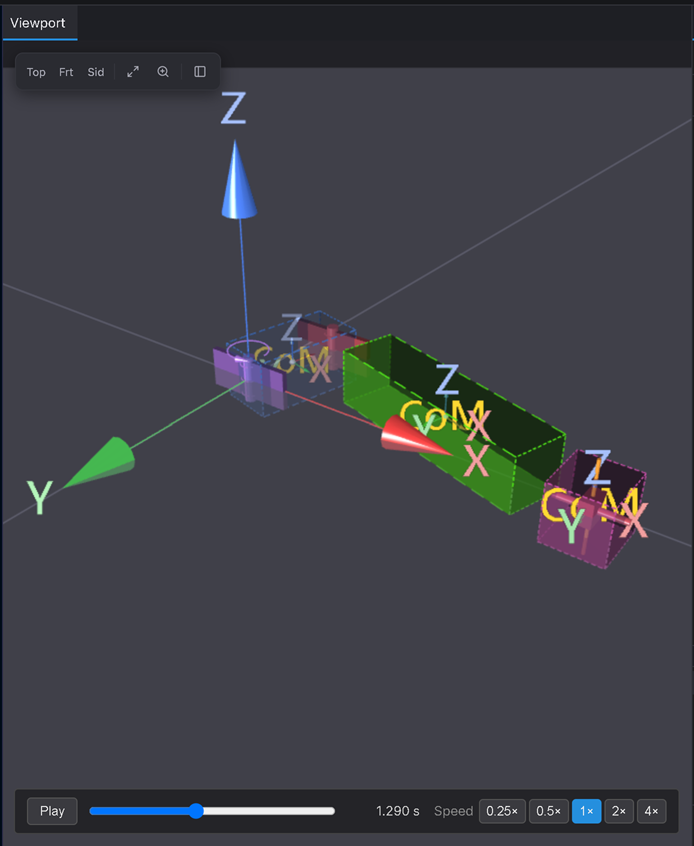
Expected: the crank spins up over the first second; the conrod tilts back and forth; and the piston reciprocates along X between about 0.105 m and 0.195 m — a stroke of 0.090 m (90 mm), exactly twice the 45 mm crank throw — completing one full out-and-back for every crank revolution. That's the engine: rotation in, straight-line reciprocation out, over the Bullet's real 90 mm stroke.
Verifiable outcome
- The piston reciprocates between X ≈ 0.105 m and X ≈ 0.195 m — a 90 mm stroke = 2 × the 45 mm crank throw, matching the real Bullet 350 spec. ✅ (Add a Distance Request from the slider to the ground pivot, Tutorial 6, to read the extremes exactly.)
- One piston out-and-back per crank revolution (1 Hz once the ramp settles at 2π rad/s). ✅
- Because the rod ratio is a realistic L/r ≈ 3.3, the conrod stays close to the bore axis — much less tilt than a stubby textbook rod. ✅
- The loop assembles and runs smoothly — the proof your constraint count is right, thanks to the In-Line (not a second Revolute) in Step 6. ✅
Troubleshooting
- It won't solve / complains about assembly or redundant constraints → almost always an over-constrained loop. Check Step 6 is an In-Line, not a Revolute — a Revolute there double-constrains the piston against the prismatic.
- The mechanism flies apart or the piston leaves the X-axis → a pivot is at the wrong global point. The pins must coincide: ground pivot (0, 0, 0), crank pin (0.045, 0, 0), conrod-to-slider and slider rail both (0.195, 0, 0).
- The crank just sits there → the Rotary Drive needs an angular-velocity drive (the Ramp). Without a drive it's a free rotary joint and nothing turns it.
- Everything's rotated the wrong way → the three pin joints use axis Z (0, 0, 1); only the slider rail uses axis X (1, 0, 0).
- Still stuck? Load Demos ▸ Slider-Crank — it's now this exact Bullet-350 model — and compare each joint's Pivot (global) and axis against yours, one at a time.