Tutorial 6 — Markers & Requests (measuring what happened)
Goal: learn BriskFyr's measurement tools — a Marker (a reference point that carries no mass) and a Request (a named channel that samples a quantity every solved frame, with a live numeric readout as you scrub). You'll re-open Tutorial 2's pendulum and, for the first time, get exact numbers instead of eyeballing the playback.
Time: ~20 minutes · Prerequisites: Tutorial 2 (the pendulum model: pivot at (0,0,2), mass node at (0.2,0,1.0), Revolute with a horizontal axis).
Concept — a point that isn't a body, and a channel that isn't a plot
Everything you've measured so far has been by eye — scrub the playback and judge the position or the angle. Two tools make this exact:
- A Marker is a point in space with no mass and no motion of its own — it exists purely so you have somewhere to measure from or to. Place one on a body (it then moves with the body, at a chosen offset) or at a fixed absolute location.
- You don't always need a Marker, though — for a fixed point in empty space, a Request can anchor directly to a Ground point (just X/Y/Z), no Marker required. Markers earn their keep when the point you care about isn't a body's own node — e.g. an offset point on a swinging body.
- A Request (Distance / Velocity / Acceleration / Force / Angle) samples a quantity every frame, between two such anchors (or from a joint). Add one and its dialog shows a live "Current: … @ frame N" readout that updates as you scrub — the exact numeric check the earlier tutorials could only approximate by eye. Requests are also exportable (Solve ▸ Export .bfreq) and — Tutorial 7 — plottable.
Re-open the pendulum
1. Rebuild (or re-open) Tutorial 2's model
If you still have it saved, open it. Otherwise rebuild in 60 seconds: Node at (0.2, 0, 1.0) → Rigid Body (1 kg) on it → Revolute joint to Ground with Pivot (0, 0, 2) and Hinge axis (0, 1, 0) → confirm gravity is on.
Expected: the same pendulum as Tutorial 2 — released from a small offset, it swings with a ≈2.0 s period.
Add a Marker
2. Mark a point on the swinging body
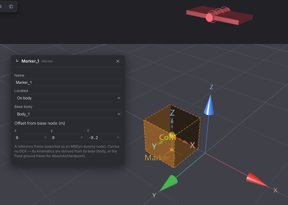
Build ▸ Marker. With the body selected, it attaches on that body at a small offset. Open it in the Inspector and set Relative offset → (0, 0, −0.2) — 0.2 m below the body's own node, as if marking the bottom tip of the bob.
Expected: a marker glyph appears just below the body, and moves with it as the pendulum swings (unlike a plain node, it carries no mass and adds no DOF).
Distance Request — is the arm actually rigid?
3. Add a Distance Request
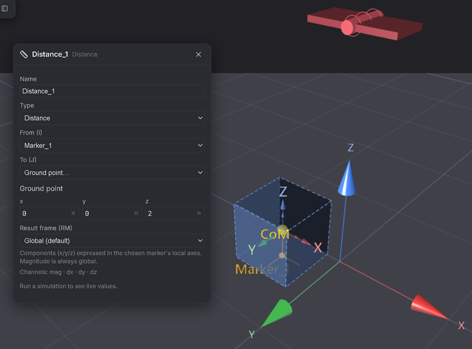
Requests ▸ Distance. It opens already pointing From (I) at your new Marker (the first marker/body in the model is auto-selected). Set To (J) → Ground point (0, 0, 2) — the pivot.
Expected: this measures the live distance between the pivot and the marker on the bob — which, for a rigid pendulum arm, should never change, swing after swing.
4. Solve and read the live value
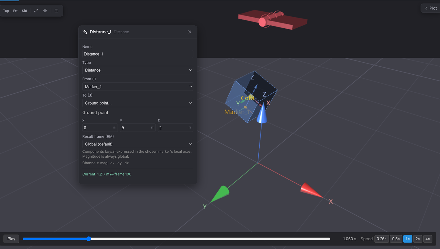
Solve (Duration 5 s, as in Tutorial 2). With the Distance Request's dialog open, scrub the playback through a full swing.
Expected: the "Current: … m @ frame N" readout stays at essentially the same value throughout (≈1.22 m — the straight-line distance from the pivot at (0,0,2) to the marker at (0.2,0,0.8): √(0.2² + 1.2²) = 1.217 m). That constancy is the proof the arm is rigid — a stretchy or slipping link would show the number drift.
Angle Request — swing angle instead of eyeballing playback
5. Add an Angle Request
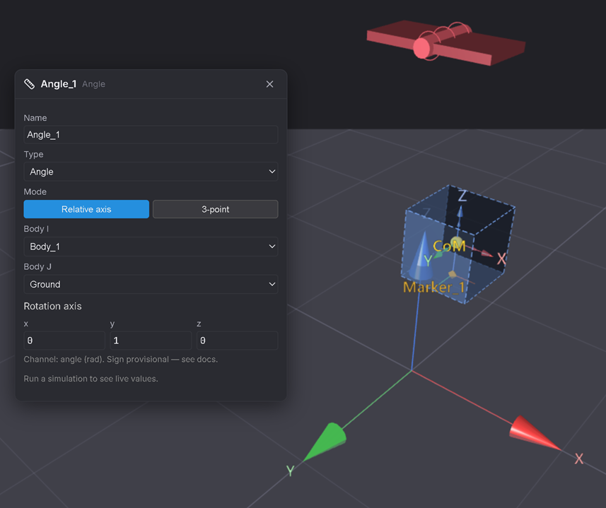
Requests ▸ Angle. Leave mode as Relative axis; set Body I = your pendulum body, Body J = Ground, Axis → (0, 1, 0) (the hinge axis — same axis you set on the Revolute in Tutorial 2).
Expected: this reads the pendulum's swing angle directly, instead of you judging it by eye against the grid.
6. Confirm it against Tutorial 2's numbers
Scrub to the pendulum's release point (t = 0) and read the angle — it should match your original offset (≈11°, from the 0.2 m sideways / 1.0 m down node placement). Then scrub forward to the next time it reaches (approximately) that same magnitude, on the other side of the swing — the time between them is half the period, so doubled it should land back near Tutorial 2's ≈2.0 s.
Expected: an exact numeric confirmation of what Tutorial 2 only measured by eye on the playback bar.
Force Request — the joint's reaction, in numbers
7. Add a Force/Torque Request on the Revolute
Requests ▸ Force/Torque. It auto-selects the first joint (your Revolute); set Quantity → Force, Side → Reaction.
Expected: this is the exact same reaction you saw as an arrow in Tutorial 3 — now as a live number.
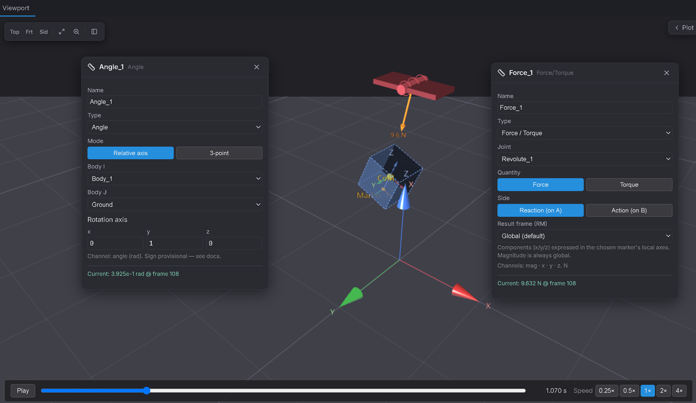
8. Confirm the peak is at the bottom of the swing
Solve, then scrub to the pendulum's lowest point (where it moves fastest) versus one of its extremes (momentarily still).
Expected: the reaction force reads noticeably higher at the bottom (holding up the weight and supplying the centripetal pull for the curved path) than at the extremes (holding up the weight alone). This is the same physical fact Tutorial 3's overlay showed you visually — now with a number attached.
Verifiable outcome
- Distance (pivot → bob) stays constant through the whole swing — confirms a rigid link, no stretch/slip. ✅
- Angle matches the release offset (≈11°) at t = 0, and the time between matching peaks confirms Tutorial 2's ≈2.0 s period — this time by number, not eye. ✅
- Force (joint reaction) peaks at the bottom of the swing, lowest at the extremes — same physics as Tutorial 3's overlay, now quantified. ✅
Export a record
Solve ▸ Export .bfreq writes every Request's full time history to a CSV — useful for a permanent record, or to check the numbers outside the app. (Velocity and Acceleration Requests work the same way as Distance — same From/To anchors, same live readout — try a Velocity Request on the same two anchors and watch it swing between fastest at the bottom and momentarily zero at each extreme.)
Troubleshooting
- The Distance Request's live readout says "Run a simulation to see live values" → you need to Solve first; the readout only appears once there's a result to sample.
- The Angle Request reads a completely different axis than expected → make sure Axis matches the Revolute's own Hinge axis (0, 1, 0) from Tutorial 2 — a mismatched axis measures rotation about the wrong direction.
- A request's "To (J)" won't let you type coordinates → you need to pick "Ground point…" from that dropdown first; it's blank/disabled until you do.
- The Marker doesn't seem to move with the body → confirm its placement is on_body (attached in Step 2, not later switched to Absolute), and that you selected the pendulum body before clicking Marker so it auto-attached there.