Tutorial 2 — Build a Pendulum
Goal: add your first joint. You'll hinge a body to ground, let gravity swing it, and confirm the swing period matches the textbook pendulum formula. This is where a static body becomes a mechanism.
Time: ~15 minutes · Prerequisites: Tutorial 1 (you can add a Node, a Rigid Body, set the run, Solve, and play back), with BriskFyr open in your browser and signed in.
Concept — a joint removes degrees of freedom
In Tutorial 1 the body had all 6 DOF free and fell. A revolute joint (a hinge) removes 5 of them — it pins the body to a fixed point and allows only one rotation, about the hinge axis. That single remaining DOF, driven by gravity, is a pendulum.
For a small swing, the period depends only on the arm length L and gravity g — not on the mass and not on the amplitude:
T = 2π √(L / g)
With L = 1 m and g = 9.81 m/s², that's T ≈ 2.0 s per swing. We'll measure it and check.
Two more ideas this model shows: - The hinge axis must be horizontal. Gravity points down (−Z). A hinge can only swing if its axis is perpendicular to gravity — a vertical axis produces a moment of zero and the pendulum just hangs there. (This is the #1 thing to get right below.) - No damping → no decay. With nothing to dissipate energy, the amplitude stays constant forever — energy is conserved.
Steps
1. Place the pendulum mass
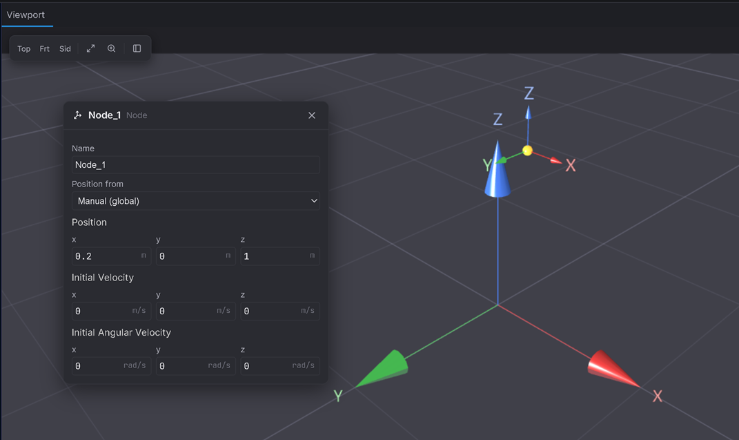
Add a Node (Build ▸ Node). Select it in the Inspector and set its Position to X = 0.2, Y = 0, Z = 1.0.
Expected: the node sits 1 m below — and 0.2 m to one side of — where the hinge will go (at Z = 2). That sideways offset is the pendulum "pulled back" a small angle (~11°) so it has somewhere to swing from.
2. Add the body
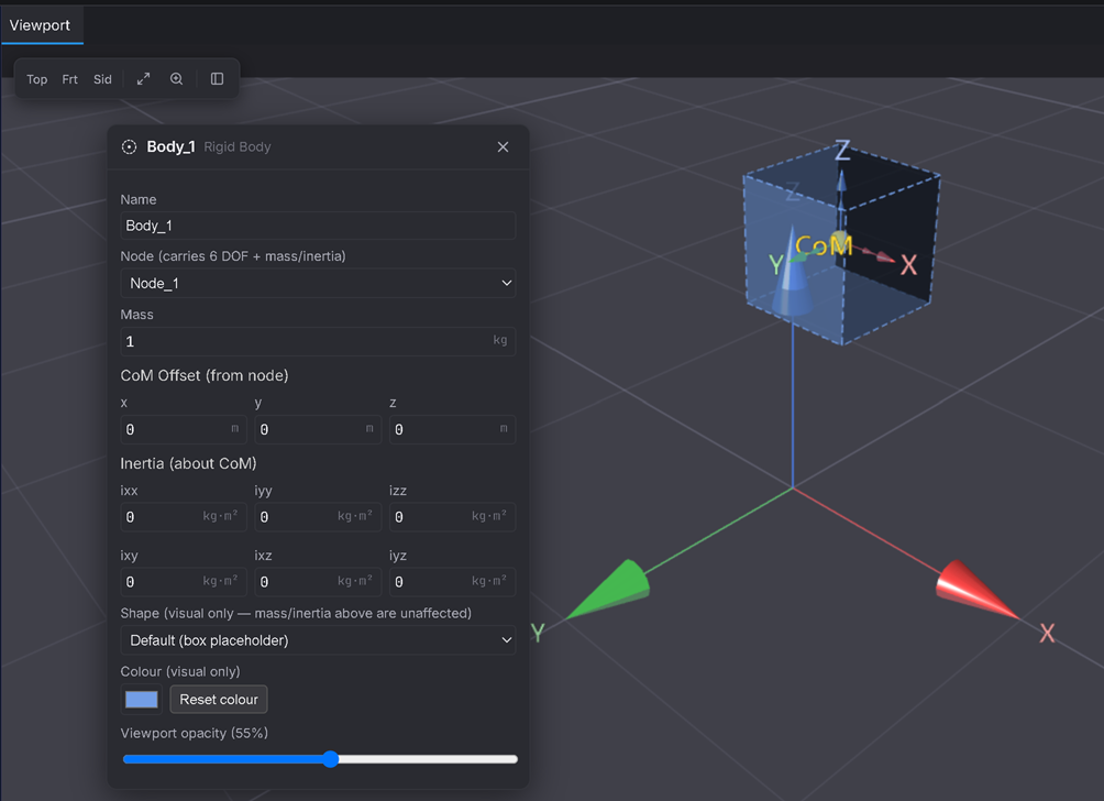
Add a Rigid Body (Build ▸ Rigid Body) on that node — mass 1 kg is fine.
Expected:
Body_1appears on the node. (The pendulum period is independent of mass — Step 7 confirms it. Optional: in the body's Inertia fields, set the three values to ~0 for an ideal point-mass pendulum; leaving the defaults makes it a "compound" pendulum with a <1 % period correction.)
3. Add the hinge — and aim it correctly (the crux)
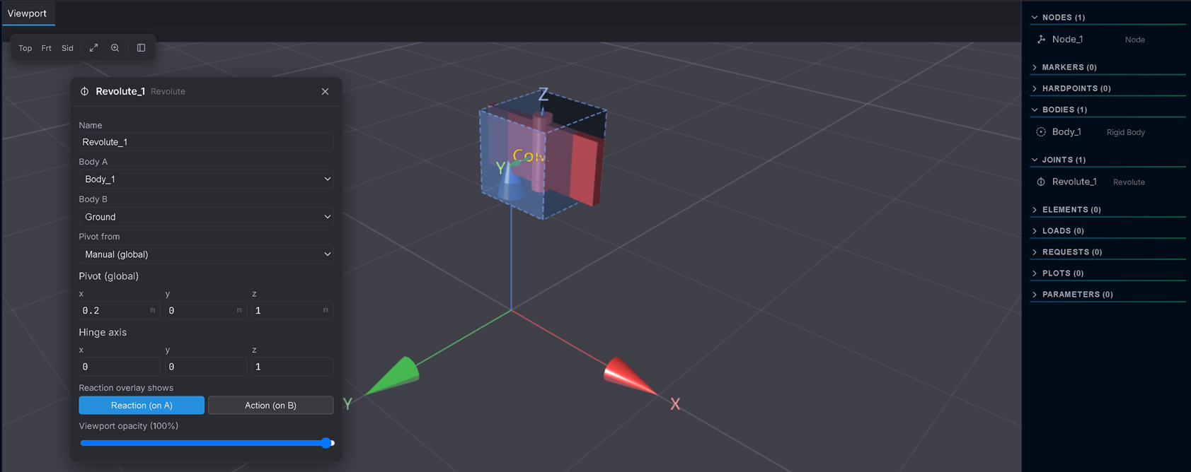
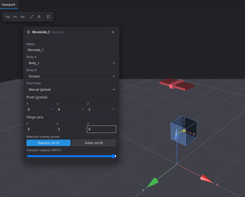
Add a Revolute joint (Joints ▸ Revolute). It hinges Body_1 to Ground. Now open the joint in the Inspector and set two fields:
- Pivot (global) → X = 0, Y = 0, Z = 2. This lifts the hinge point up to the top, 1 m above the mass. (A fresh Revolute puts the pivot at the body's own location — you're moving it up to where a real pendulum hangs from.)
- Hinge axis → X = 0, Y = 1, Z = 0 (horizontal).
Expected: a hinge glyph appears at (0, 0, 2) with its axis pointing sideways (along Y). The body now reads as hanging from that point.
⚠️ This is the step that makes or breaks the tutorial. A new Revolute defaults to a vertical axis
(0, 0, 1). With gravity pointing straight down, a vertical hinge has nothing to swing about — the model will just sit still. Setting the axis to horizontal (0, 1, 0) is what lets gravity swing it.
4. Confirm gravity
Settings ▸ Environment — gravity is on by default (Magnitude 9.81, Direction 0/0/−1). No change needed.
5. Set the run
Solve tab ▸ Simulation — Duration = 5 s, Time step = 0.01 s. (Five seconds is ~2½ swings at T ≈ 2 s.)
6. Solve and play back
Click Solve. When the playback bar appears, press Play.
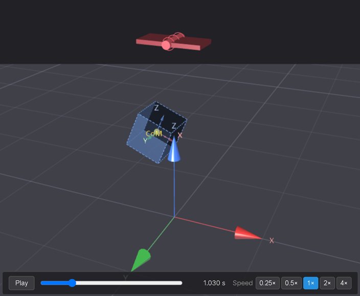
Expected: the body swings back and forth about the hinge like a pendulum, in the X–Z plane. The amplitude stays the same swing after swing — it doesn't wind down.
7. Measure the period
Use the playback bar's time read-out to time one full swing: scrub to a moment when the pendulum is at one extreme (momentarily stopped, furthest out), note the time, then scrub to the next time it's at that same extreme. The difference is the period.
Expected: about 2.0 seconds per full swing.
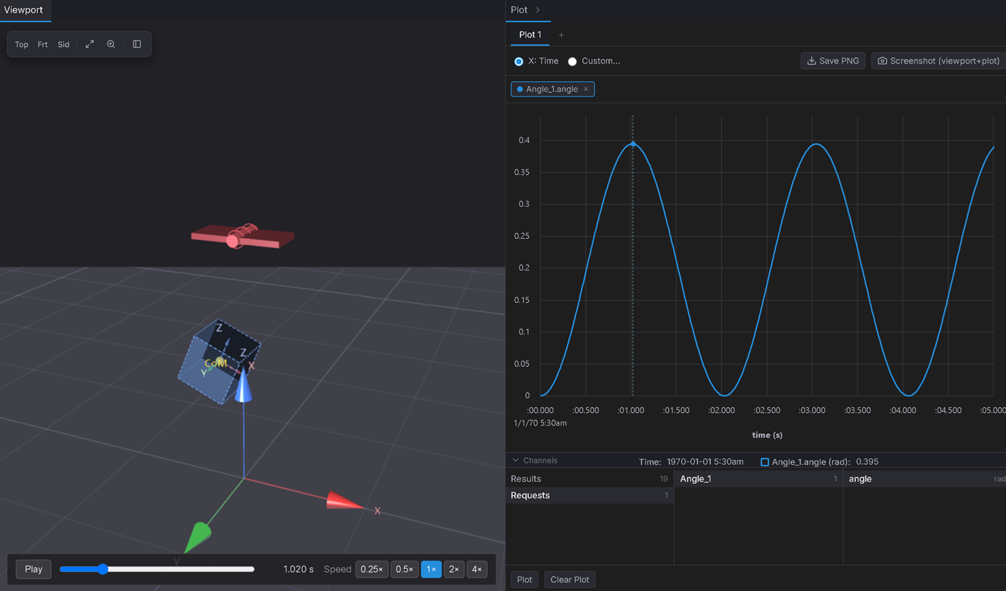
Precise option (previews Tutorial 6's measuring tools + Tutorial 7's plotting): add an Angle Request on the body, Solve, and plot the angle vs. time — the peaks are one period apart, and you can read ≈ 2.0 s directly.
Verifiable outcome
- Period: ≈ 2.0 s, matching T = 2π√(L/g) = 2π√(1 / 9.81) = 2.006 s — within a few percent. ✅
- Constant amplitude: the swing doesn't decay, because there's no damping (energy is conserved). ✅
- Change the mass and re-Solve — the period doesn't change. Change the arm length (move the mass node closer to / further from the hinge) and it does (∝ √L).
You've built a one-DOF mechanism and validated it against analytical physics.
Troubleshooting
- The pendulum doesn't move at all → the hinge axis is still vertical
(0, 0, 1). Set Hinge axis = (0, 1, 0) (Step 3). This is by far the most common miss. - It hangs straight down and barely moves → the mass node is directly under the hinge (no starting offset). Give it the X = 0.2 offset (Step 1).
- It swings in a full circle instead of back and forth → you started it from too large an angle (or gave it a velocity); keep the offset small for a clean pendulum.